
 EN
EN
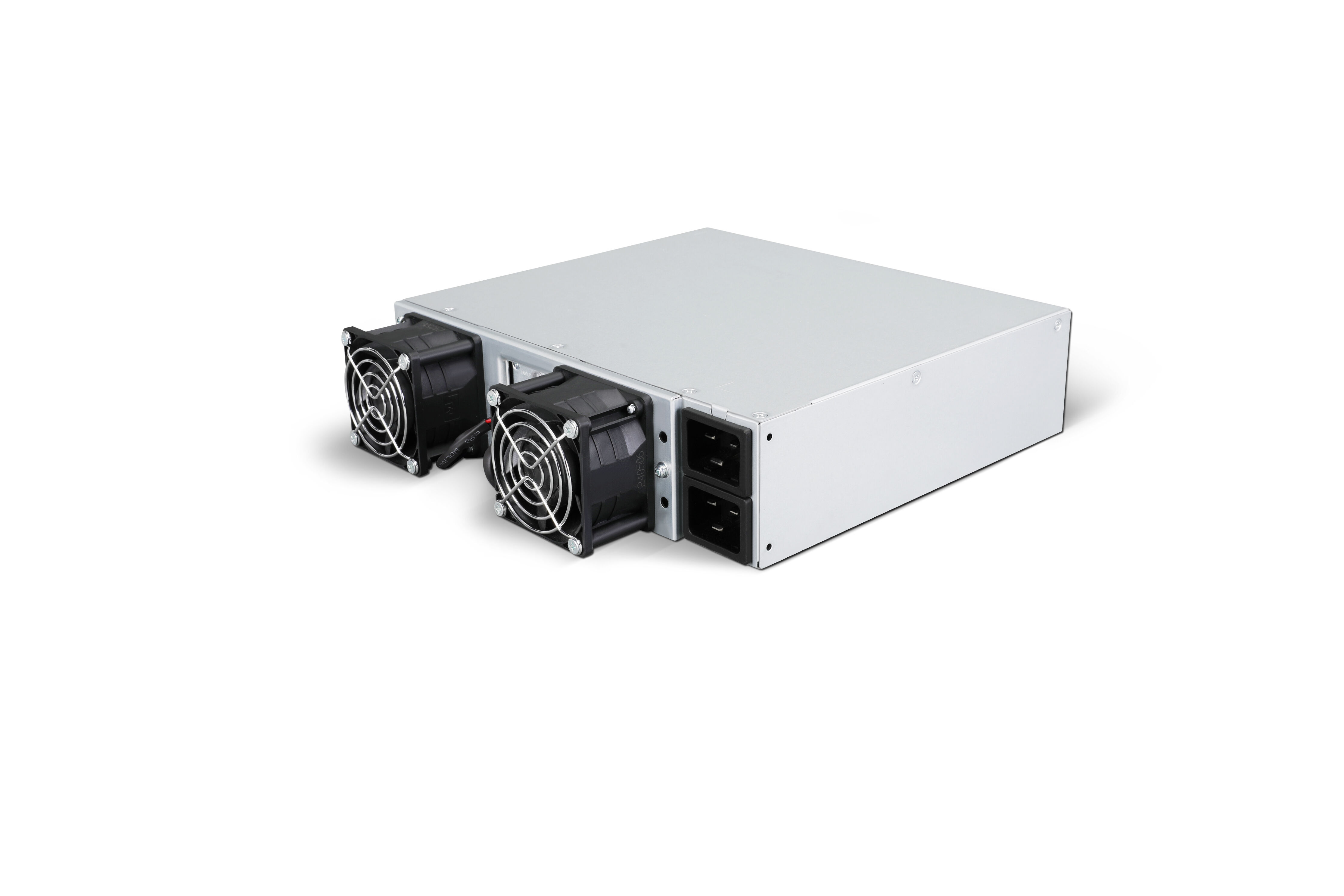
A 130 கிலோவாட் ஆற்றல் சேமிப்பு PCS எந்தவொரு நடுத்தர அளவு ஆற்றல் சேமிப்பு அமைப்பின் செயல்பாட்டு மையத்திலும் அமைந்து, பேட்டரி வங்கிக்கும் மின் வலையிற்கும் இடையே மின்சக்தியின் இருதிசை ஓட்டத்தை துல்லியமாக மேலாண்மை செய்கிறது. இந்த அலகு சரியான பராமரிப்பில் இருந்தால், அது நிலையான அதிர்வெண் பதிலளிப்பையும், துல்லியமான மின்னழுத்த ஒழுங்குப்படுத்தலையும், மற்றும் முழு சேமிப்பு சொத்து அதன் தரப்பட்ட திறனில் செயல்படுவதை உறுதிப்படுத்தும் நம்பகமான மின்னூட்ட-மின்னிறக்க சுழற்சியையும் வழங்குகிறது. இந்த அலகு பராமரிக்கப்படாமல் விடப்பட்டால், சிறிய அளவிலான கூறு மோசமாகுதல் கூட மின் வலை இணைப்பு பிழைகள், பாதுகாப்பு தடைகள் மற்றும் விலையுயர்ந்த நிறுத்தங்களுக்கு வழிவகுக்கும், இது முக்கிய மூலதன முதலீட்டின் வருவாயைக் குறைக்கிறது.
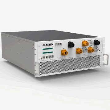
வலையமைப்புடன் சிறந்த வழியில் இணைந்திருத்தலுக்காக 130kW ஆற்றல் சேமிப்பு PCS-ஐ பராமரித்தல் என்பது ஒரு தனிப்பட்ட நிகழ்வு அல்ல, மாறாக மின்சார ஆய்வு, வெப்ப மேலாண்மை, ஃபர்ம்வேர் ஒழுங்குமுறை மற்றும் பாதுகாப்பு அமைப்பு சரிபார்ப்பு ஆகியவற்றை உள்ளடக்கிய அமைப்புசார், தொடர்ச்சியான ஒழுங்குமுறையாகும். இந்தக் கட்டுரையானது, 130kW ஆற்றல் சேமிப்பு PCS-ஐ வலையமைப்பு குறியீடுகளின் எல்லைக்குள் இயக்கி, அதன் சேவை ஆயுளை நீட்டித்தல் மற்றும் முழு திட்ட வாழ்நாள் முழுவதும் திட்டமிடப்படாத நிறுத்தங்களைக் குறைத்தல் ஆகியவற்றை உறுதிப்படுத்தும் பயன்பாட்டு பராமரிப்பு பணிமுறையை விளக்குகிறது.
வலையமைப்புடன் இணைந்திருக்கும் போது 130kW ஆற்றல் சேமிப்பு PCS-இன் செயல்பாடுகளைப் புரிந்துகொள்ளுதல்
பராமரிப்பு பாதுகாக்க வேண்டிய முக்கிய செயல்பாடுகள்
130 கிலோவாட் ஆற்றல் சேமிப்பு PCS (பவர் கன்வர்டர் ஸ்டேஷன்) மின்னழுத்த-மின்னோட்ட (AC-DC) மற்றும் மின்னோட்ட-மின்னழுத்த (DC-AC) மாற்றத்தைச் செய்கிறது, இதன் மூலம் பேட்டரி அமைப்பு தினசரி குறைந்த தேவை நேரங்களில் வலையின் மிகை ஆற்றலை உறிஞ்சிக் கொள்ளவும், உச்ச தேவை நேரங்களில் அல்லது வலை ஆதரவு நிகழ்வுகளின் போது சேமிக்கப்பட்ட ஆற்றலை மீண்டும் வலையில் செலுத்தவும் முடியும். இது தற்காலிக மின்சக்தி தரத்தை மேம்படுத்தும் செயல்பாடுகளையும் மெய்நேரத்தில் செயல்படுத்துகிறது — எ.கா., திரும்பு மின்சக்தி ஈடுசெய்தல், ஒலிக்குறியீட்டு (ஹார்மோனிக்) அடக்கம் மற்றும் மின்சக்தி ஏற்ற/இறக்க வேகக் கட்டுப்பாடு. இந்தச் செயல்பாடுகள் ஒவ்வொன்றும் உள் பாகங்களின் நிலைமையைப் பொறுத்தது; எந்தவொரு தேய்மானமும் அலகின் வலையுடனான இணைப்பை நேரடியாகப் பாதிக்கும்.
வலை இயக்குநர்கள், அதிரடியாக அதிர்வெண் விலகல் சிக்னல்களுக்கு மில்லிசெகண்டுகளில் பதிலளிக்க சேமிப்பு சொத்துகளை தினசரி தேவையாகக் கேட்கின்றனர். கட்டுப்பாட்டு சுழற்சியின் சரியான அளவுகோல் மாறிவிட்ட அல்லது DC பஸ்ஸில் பழைமையான கேபாசிட்டர்களைக் கொண்ட 130 கிலோவாட் ஆற்றல் சேமிப்பு PCS மெதுவாகவோ அல்லது துல்லியமின்றியோ பதிலளிக்கும், இது வலை குறியீடுகளுக்கு ஏற்பாடு செய்யப்படாத நிலையை ஏற்படுத்தி, தண்டனைகளைத் தூண்டக்கூடும். எனவே, பராமரிப்பு நடைமுறைகள் தவறுகளைத் தடுப்பதற்கு மட்டுமல்லாமல், வலை இணைப்புக்கு தேவையான பதிலளிப்புத் துல்லியத்தைப் பாதுகாப்பதற்காகவும் வடிவமைக்கப்பட வேண்டும்.
இந்த செயல்பாட்டு சார்புகளைப் புரிந்துகொள்வது, பராமரிப்பு குழுக்களுக்கு பணிகளை சரியான முறையில் முன்னுரிமை அளிக்க உதவுகிறது. 130kW ஆற்றல் சேமிப்பு PCS-ஐ பொதுவான மின்சார எலக்ட்ரானிக்ஸ் அலமாரி எனக் கருதுவதற்குப் பதிலாக, தொழில்நுட்ப வல்லுநர்கள் அதை ஒரு துல்லியமான வலையமைப்பு இணைப்பு சாதனமாக அணுக வேண்டும்; இதில் காலிப்ரேஷன் (அளவியல்), சுத்தம் மற்றும் கூறுகளின் நிலை ஆகியவை அனைத்தும் வலையமைப்பு செயல்திறன் அளவீடுகளில் அளவிடக்கூடிய விளைவுகளை ஏற்படுத்துகின்றன.
கவனம் தேவைப்படும் முக்கிய உள் உப-அமைப்புகள்
130kW ஆற்றல் சேமிப்பு PCS-இன் முக்கிய உப-அமைப்புகளில் IGBT-அடிப்படையிலான மாற்றி நிலை, DC பஸ் கேபாசிட்டர் வங்கி, LCL வடிகட்டி கட்டமைப்பு, கட்டுப்பாட்டு பலகை மற்றும் DSP செயலி, குளிரூட்டும் அமைப்பு, பாதுகாப்பு ரிலே மற்றும் கண்காணிப்பு சுற்றுகள் ஆகியவை அடங்கும். ஒவ்வொரு உப-அமைப்பும் தனித்தனியான தீவிரமாக்கல் வழிமுறை மற்றும் பராமரிப்பு இடைவெளியைக் கொண்டுள்ளது. இவற்றை ஒருங்கிணைந்த அமைப்பாகவும், தனித்தனியான கூறுகளாக அல்லாமலும் கருதுவதுதான் திறம்பட பராமரிப்பு திட்டமிடலின் அடிப்படையாகும்.
IGBT மாட்யூள்கள் மின்சாரத்தை AC மற்றும் DC ஆகிய இரு ஆவினங்களுக்கும் இடையே மாற்றும் அதிர்வெண்-அதிக அளவு ஸ்விட்சிங்கை கையாளுவதால், அவை குறிப்பிடத்தக்க முக்கியத்துவம் வாய்ந்தவையாகும். தொடர்ச்சியான ஸ்விட்சிங் சுழற்சிகளால் ஏற்படும் வெப்ப அழுத்தம், இந்த மாட்யூள்களுக்குள் உள்ள சோல்டர் பந்தங்களை படிப்படியாக சீர்குலைத்து, ஆன்-ஸ்டேட் எதிர்ப்பு மற்றும் ஸ்விட்சிங் இழப்புகளை அதிகரிக்கிறது. IGBT நிலையின் வழக்கமான வெப்ப படமாக்கல் மற்றும் காலாவதியான மின்சார பண்பியல் ஆய்வுகள் இந்த சீர்குலைவை ஒரு தவறு ஏற்படுவதற்கு முன்பே கண்டறிய பராமரிப்பு குழுக்களுக்கு உதவுகின்றன.
வலையிணைப்பு இணைப்பு புள்ளிக்கு முன்பாக வெளியீட்டு மின்னோட்ட அலைவடிவத்தை சீராக்கும் LCL வடிகட்டி, பராமரிப்பு அட்டவணைகளில் பெரும்பாலும் புறக்கணிக்கப்படுகிறது. இருப்பினும், வடிகட்டி கட்டமைப்பில் உள்ள தூண்டியின் உள்ளுறை நிரப்புதல், மின்தேக்கியின் ESR விலகல் மற்றும் தளர்ந்த முனை இணைப்புகள் ஆகியவை வலையிணைப்பு குறியீடுகளின் வரம்புகளை மீறும் ஹார்மோனிக் திரிபை ஏற்படுத்தலாம். கடுமையான மின்சாரத் தரத் தேவைகளுக்கு உட்பட்டு 130kW ஆற்றல் சேமிப்பு PCS-ஐ இயக்கும் எந்தவொரு அமைப்பிலும், LCL வடிகட்டியை வழக்கமான பரிசோதனை சுழற்சிகளில் சேர்த்தல் அவசியமாகும்.
தடுப்பு பராமரிப்பு அட்டவணையை உருவாக்குதல்
தொடர்ச்சியான கிரிட் தயாரிப்புக்கான தினசரி மற்றும் வாராந்திர சரிபார்ப்புகள்
130kW ஆற்றல் சேமிப்பு PCS-க்கான தினசரி பராமரிப்பு, SCADA அல்லது உள்ளூர் HMI டாஷ்போர்டில் முந்தைய சரிபார்ப்புக்குப் பிறகு பதிவு செய்யப்பட்ட ஏதேனும் செயலில் உள்ள அலார்ம்கள், எச்சரிக்கை குறியீடுகள் அல்லது அளவுரு விலகல்களை முதலில் பார்வையிடுவதை உள்ளடக்கியது. சரிபார்க்க வேண்டிய முக்கிய அளவுருக்களில் DC பஸ் மின்னழுத்த நிலைத்தன்மை, வெளியீட்டு மின்னோட்ட THD அளவீடுகள், இன்வெர்டர் வெப்பநிலை அளவீடுகள் மற்றும் ஏதேனும் கிரிட் ஒத்திசைவு தவறு குறியீடுகள் ஆகியவை அடங்கும். இவற்றை முறையாக கண்டறிவதன் மூலம் சிறிய மாறுபாடுகள் உச்ச கிரிட் தொடர்பு நேரங்களில் பாதுகாப்பு ட்ரிப்களாக மாறுவதைத் தடுக்கலாம்.
வாராந்திர சரிபார்ப்புகளில் கேபினெட்டின் வெளிப்புறத்தை ஈரப்பதம் புகுதல், பூச்சிகள் அல்லது பாம்புகள் புகுதல், கேபிள் நுழைவுகள் மற்றும் கான்டுயிட் சீல்களில் உள்ள இயற்பியல் சேதம் ஆகியவற்றின் கண்ணுக்குத் தெரியும் அறிகுறிகளை விசுவாசமாக ஆய்வு செய்ய வேண்டும். குளிரூட்டும் விசிறியின் இயக்கம், கண்கேட்டு மற்றும் கண்காணிப்பு அமைப்பின் மூலம் சரிபார்க்கப்பட வேண்டும்; ஏனெனில், விசிறியின் பேரிங் தேய்மானம் திறந்த வெளியில் அல்லது அரை-திறந்த வெளியில் பொருத்தப்பட்ட 130kW ஆற்றல் சேமிப்பு PCS-ல் வெப்ப நிறுத்தத்திற்கு மிகவும் பொதுவான காரணங்களில் ஒன்றாகும்.
இந்த தினசரி மற்றும் வாராந்திர கவனிப்புகளை அமைப்புசார் பராமரிப்பு பதிவில் பதிவு செய்வது, மெதுவான தேய்மான முறைகளை அடையாளம் காண மிகவும் மதிப்புமிக்க ஒரு போக்குத் தரவுத்தளத்தை உருவாக்குகிறது. ஒரு முறை மட்டும் காணப்படும் வெப்பநிலை மாறுபாடு தனியாக எதுவும் குறிப்பிடத்தக்கது அல்ல; ஆனால் ஆறு வாரங்களுக்கு மேலாக தொடர்ச்சியான ஏறுமுகப் போக்கு என்பது, குளிரூட்டும் அமைப்பு அல்லது குறிப்பிட்ட மின்சக்தி மாட்யூல் அடுத்த அதிக தேவை கொண்ட கிரிட் தொடர்பு காலத்திற்கு முன்பாக இடையீடு செய்யப்பட வேண்டும் என்பதை தெளிவாகக் குறிக்கிறது.
மாதாந்திர மற்றும் காலாண்டு ஆய்வு நடைமுறைகள்
மாதாந்திர ஆய்வுகளில் 130kW ஆற்றல் சேமிப்பு PCS-இல் உள்ள அனைத்து உயர்-மின்னோட்ட பஸ் பார் இணைப்புகள் மற்றும் டெர்மினல் பிளாக்குகளின் டார்க் சரிபார்ப்பு அடங்கும். வெப்ப சுழற்சி காரணமாக உலோக பிணைப்புகள் நேரத்துடன் தளர்ந்து விடும்; மேலும், அதிகரித்த மின்தடை கொண்ட ஒரு இணைப்பு உள்ளூர் வெப்பத்தை உருவாக்கும், இது மின்காப்பு தேய்மானத்தை விரைவுபடுத்தும் மற்றும் இறுதியில் விற்று தவறு (arc fault) ஏற்படுத்தக்கூடும். இந்தப் பணிக்கு, சரிசெய்யப்பட்ட டார்க் விச்சு மற்றும் தயாரிப்பாளர் குறிப்பிட்டுள்ள டார்க் மதிப்புகளைப் பின்பற்றுவது கட்டாயமாகும்.
காலாண்டு தொழில்நுட்ப பராமரிப்பின் போது, கேபினெட்டின் உள்ளே சுமை நிலையில் முழுமையான வெப்ப படம் எடுக்கப்பட வேண்டும். இந்த படம் ஐஜிபிடி (IGBT) மாட்யூள்கள், டிசி பஸ் கேபாசிட்டர்கள், பஸ் பார் இணைப்புகள் மற்றும் வடிகட்டி பாகங்களை உள்ளடக்கியிருக்க வேண்டும். இந்த படத்தில் கண்டறியப்பட்ட வெப்ப மாறுபாடுகளை, மின்சார செயல்திறன் பதிவுகளுடன் ஒப்பிட்டு, அந்த வெப்ப அடையாளம் திறன் அல்லது வெளியீட்டுத் தரத்தில் அளவிடக்கூடிய மாற்றத்துடன் தொடர்புடையதா என தீர்மானிக்க வேண்டும்.
காலாண்டு இடைவெளிகள் என்பது 130 கிலோவாட் ஆற்றல் சேமிப்பு PCS-ன் காற்று உள்ளீட்டு வடிகட்டிகள் மற்றும் வெப்பச் சிகிச்சை விளிம்புகளைச் சுத்தம் செய்வதற்கு ஏற்ற நேரமாகும். வெப்பச் சிகிச்சை விளிம்புகளில் தூசி சேர்வது வெப்ப எதிர்ப்பை அதிகரித்து, குளிரூட்டும் அமைப்பை அதிக வேலை செய்ய வைக்கிறது; இது விசிறியின் ஆயுளைக் குறைக்கிறது மற்றும் அதிக மின்திறன் கிரிட் தொடர்பு நிகழ்வுகளின் போது வெப்ப திறன் குறைவு ஏற்படுவதற்கான அபாயத்தை அதிகரிக்கிறது. தூசியுள்ள அல்லது தொழில்துறை சூழல்களில், இந்த சுத்தம் செய்யும் இடைவெளியை மாதாந்திரமாகக் குறைக்க வேண்டியிருக்கலாம்.
ஃபர்ம்வேர், கட்டுப்பாட்டு அமைப்பு மற்றும் பாதுகாப்பு ரிலே பராமரிப்பு
கிரிட் தொடர்பு துல்லியத்திற்காக கட்டுப்பாட்டு அமைப்பை சரியாக சீரமைத்து வைத்திருத்தல்
130 கிலோவாட் ஆற்றல் சேமிப்பு PCS-ன் கட்டுப்பாட்டு ஃபர்ம்வேர், வலையின் அதிர்வெண் விலகல்கள், மின்னழுத்த வீழ்ச்சிகள் மற்றும் ஆற்றல் மேலாண்மை அமைப்பிலிருந்து வரும் கட்டளைகளுக்கு அலகு எவ்வாறு பதிலளிக்கிறது என்பதை நிர்ணயிக்கிறது. நேரத்துடன், தயாரிப்பாளரின் ஃபர்ம்வேர் புதுப்பிப்புகள் மேம்படுத்தப்பட்ட வலை இணைப்பு வழிமுறைகள், மேம்படுத்தப்பட்ட பாதுகாப்பு தர்க்கம் அல்லது அறியப்பட்ட கட்டுப்பாட்டு சுழற்சி நிலையின்மைகளுக்கான திருத்தங்களை அறிமுகப்படுத்தலாம். ஒரு கட்டுப்பாட்டு ஃபர்ம்வேர் புதுப்பிப்பு செயல்முறையை கண்டிப்பாக பின்பற்றுவதன் மூலம், அலகு எப்போதும் கிடைக்கக்கூடிய மிகச் சரியான மற்றும் நிலையான கட்டுப்பாட்டு நடத்தையுடன் இயங்குகிறது.
130 கிலோவாட் ஆற்றல் சேமிப்பு PCS-க்கு ஏதேனும் ஃபர்ம்வேர் புதுப்பிப்பை பயன்படுத்துவதற்கு முன், பராமரிப்பு குழு வெளியீட்டு குறிப்புகளை கவனமாக பார்வையிட வேண்டும், தற்போதைய கட்டமைப்பு அளவுருக்களை காப்பு நகலெடுக்க வேண்டும், மேலும் அலகை வலை கடமைகளை பாதிக்காமல் ஆஃப்லைனில் எடுத்துக்கொள்ளக்கூடிய திட்டிடப்பட்ட பராமரிப்பு நேரத்தில் புதுப்பிப்பை திட்டமிட வேண்டும். புதுப்பிப்பிற்குப் பிந்தைய தொழிற்சாலை சோதனை சரிபார்ப்புகள், சாய்வு அமைப்புகள், வேக மாற்ற வீதங்கள் மற்றும் தடையில்லா மின்சக்தி வளைவுகள் உள்ளிட்ட அனைத்து வலை இணைப்பு அளவுருக்களும் சரியாக மீட்டெடுக்கப்பட்டுள்ளன என்பதை உறுதிப்படுத்த வேண்டும்.
கட்டுப்பாட்டு வளைய சரிபார்ப்பு ஆண்டுதோறும் வலையின் இணைப்புப் புள்ளியில் இணைக்கப்பட்ட மின்சக்தி பகுப்பாய்வி மூலம் சரிபார்க்கப்பட வேண்டும். இந்தச் சோதனை 130kW ஆற்றல் சேமிப்பு PCS-இன் உண்மையான பதிலளிப்பு நேரத்தையும், அதன் திட்டமிடப்பட்ட அமைப்பு மதிப்புகளுக்கு எவ்வளவு துல்லியமாக இயங்குகிறது என்பதையும் அளவிடுகிறது; இதன் மூலம், அலகின் உண்மையான வலை இணைப்பு செயல்திறன் அதன் திருத்தமான தன்மைகளுடன் பொருந்துகிறது என உறுதிப்படுத்தப்படுகிறது. ஏற்றுக்கொள்ளக்கூடிய சாத்தியமான விலகல் வரம்பை மீறும் எந்தவொரு விலகலும் மீண்டும் சரிபார்ப்பு நடவடிக்கையைத் தூண்ட வேண்டும்.
பாதுகாப்பு ரிலே அமைப்புகளைச் சோதித்தல் மற்றும் சரிபார்த்தல்
130kW ஆற்றல் சேமிப்பு PCS-இல் உள்ள பாதுகாப்பு ரிலேக்கள், வலை குறைபாடுகள், தனிமைப்படுத்தப்பட்ட நிலைகள் (islanding conditions) மற்றும் உள் மிகை மின்னோட்ட நிகழ்வுகளுக்கு எதிரான இறுதி பாதுகாப்பு வரிசையாகும். இந்த ரிலேக்கள், அவற்றின் திறக்கும் தீவிரத்தின் மதிப்புகள் சரியாக அமைக்கப்பட்டுள்ளன எனவும், ரிலே வன்பொருள் தன்னை மாற்றிக்கொள்ளவோ அல்லது தொடர்பு சிக்கல்களை ஏற்படுத்தவோ இல்லை எனவும் உறுதிப்படுத்துவதற்காக காலாவதியாக சோதிக்கப்பட வேண்டும். உயிருள்ள குறைபாடு நிலையை ஏற்படுத்தாமல் ரிலே செயல்திறனைச் சரிபார்ப்பதற்கான தொழில்துறை தரமான முறை, ஆண்டுதோறும் இரண்டாம் நிலை ஊட்டுதல் சோதனை (secondary injection testing) ஆகும்.
ஆற்றல் சேமிப்பு PCS (130 kW) ஒன்று பரவல் மின் வலையில் இணைக்கப்பட்டிருக்கும்போது, தனிமைப்படுத்தப்பட்ட துணை-வலை (islanding) தடுப்பு மிகவும் முக்கியமானது. மின் வலை வழங்கல் தற்செயலாக நின்றுவிட்டாலும், PCS தொடர்ந்து உள்ளூர் வலையை மின்சாரத்தால் செயல்படுத்தினால், அது மின் வலை பராமரிப்பு ஊழியர்களுக்கு பாதுகாப்பு அச்சுறுத்தலை ஏற்படுத்தும்; மேலும், அந்த தனிமைப்படுத்தப்பட்ட துணை-வலையில் இணைக்கப்பட்டுள்ள சாதனங்களுக்கு சேதம் ஏற்படலாம். தனிமைப்படுத்தலைக் கண்டறியும் வழிமுறை (anti-islanding detection algorithm) தேவையான நேர விளைவுக்குள் சரியாக பதிலளிக்கிறதா என்பதை சரிபார்த்தல், ஆண்டுதோறும் நடைபெறும் பாதுகாப்பு அமைப்பு சோதனையின் கட்டாய பகுதியாகும்.
மேற்றிறன் (overvoltage), குறைத்திறன் (undervoltage), மேற்றிரும்பு (overfrequency) மற்றும் குறைத்திரும்பு (underfrequency) பாதுகாப்பு அமைப்புகள் ஒவ்வொரு ஆண்டு சோதனையின் போதும், நிறுவல் இடத்திற்கான தற்போதைய மின் வலை விதிமுறைகளுக்கு (grid-code requirements) ஏற்ப மீண்டும் மதிப்பாய்வு செய்யப்பட வேண்டும். மின் வலை விதிமுறைகள் காலாகாலமாக மீளாய்வு செய்யப்படுகின்றன; எனவே, 130 kW ஆற்றல் சேமிப்பு PCS-இன் பாதுகாப்பு அமைப்புகள் தொடக்க நிலையில் (commissioning) அமைக்கப்பட்டிருந்தாலும், அவை புதுப்பிக்கப்பட்ட விதிமுறைகளுக்கு இனி பொருந்தாமல் போகலாம். பாதுகாப்பு அமைப்புகளை நவீனமாக வைத்திருத்தல் என்பது பாதுகாப்புக்கான கடமை மட்டுமல்ல, மின் வலை விதிமுறைகளுக்கு உட்பட்டிருத்தலுக்கான தேவையுமாகும்.
வெப்ப மேலாண்மை மற்றும் சூழல் நிலைகளைக் கட்டுப்படுத்துதல்
முதன்மை சிதைவு இயக்கியாக வெப்பத்தை மேலாண்மை செய்தல்
வெப்பம் என்பது 130kW ஆற்றல் சேமிப்பு PCS-இல் உள்ள பாகங்களின் வயதாதலை இயக்கும் மிக முக்கியமான காரணியாகும். வடிவமைக்கப்பட்ட வெப்பநிலையை விட 10°C அதிகரிப்பு ஒவ்வொன்றும் எலெக்ட்ரோலிட்டிக் கேபாசிட்டர்களின் சிதைவு வீதத்தை ஏறத்தாழ இருமடங்காக்குகிறது, IGBT பாயிண்ட் சோர்வை முடுக்குகிறது, மேலும் குளிரூட்டும் விசிறிகள் மற்றும் கட்டுப்பாட்டு பலகை பாகங்களின் சேவை ஆயுளைக் குறைக்கிறது. எனவே, திறம்பட வெப்ப மேலாண்மை செய்வது என்பது வெறும் வசதிக்காக மட்டுமல்ல, மாறாக அலகின் வலையமைப்பு இணைப்புத் திறனின் நீண்டகால நம்பகத்தன்மையை நேரடியாக மேம்படுத்தும் ஒரு முக்கிய கட்டுப்பாட்டு கருவியாகும்.
130 கிலோவாட் ஆற்றல் சேமிப்பு PCS நிறுவலின் சூழல் வெப்பநிலையைத் தொடர்ந்து கண்காணித்து, அதன் தரப்படுத்தப்பட்ட இயக்க வரம்புடன் ஒப்பிட வேண்டும். நிறுவல் சூழல் வெப்பநிலை தொடர்ந்து அதிகபட்ச சூழல் வெப்பநிலை வரம்பை மீறினால், கூடுதல் காற்றோட்டம், குளிர்சாதன ஏற்பாடு அல்லது நிழல் அமைப்புகள் தேவைப்படலாம். இயக்க அலகை அதன் வெப்ப எல்லையின் ஓரத்தில் தொடர்ந்து இயக்குவது அதன் சேவை ஆயுளைக் குறைத்து, வலையிணைப்பு ஒத்துழைப்பு உறுதிமொழிகளை தடைசெய்யும் வெப்ப திறன் குறைப்பு நிகழ்வுகளின் அதிர்வெண்ணை அதிகரிக்கும்.
130 கிலோவாட் ஆற்றல் சேமிப்பு PCS-இன் உள் வெப்பநிலை சென்சார்களை, கண்காணிப்பு முறையில் காட்டப்படும் வாசிப்புகள் உண்மையான கூறுகளின் வெப்பநிலைகளை துல்லியமாக எதிரொலிக்குமாறு ஆண்டுதோறும் சரிசெய்ய வேண்டும். உண்மையான வெப்பநிலையை விட 5°C குறைவாக வாசிக்கும் ஒரு சென்சார், வளரும் வெப்ப சிக்கலை மறைத்து, சேதம் ஏற்படுவதற்கு முன்பாக பாதுகாப்பு அமைப்பு பாதுகாப்பு நிறுத்தத்தைத் தூண்டுவதைத் தடுக்கும்.
ஈரப்பதம், குளிர்விப்பு மற்றும் அடைப்பு தன்மை
ஈரப்பதம் மற்றும் குளிர்ந்த காற்றில் நீர்த்துளிகள் (கண்ணீர்த்துளிகள்) ஆகியவை 130kW ஆற்றல் சேமிப்பு PCS-இன் கட்டுப்பாட்டு மின்னணு உறுப்புகள் மற்றும் மின்காப்பு அமைப்புகளுக்கு மிக முக்கியமான அச்சுறுத்தல்களாகும், குறிப்பாக கடற்கரை, வெப்ப மண்டல அல்லது உயர் உயரத்தில் அமைக்கப்பட்ட நிறுவல்களில், இரவு மற்றும் பகலில் வெப்பநிலை மாற்றங்கள் மிக அதிகமாக இருக்கும் போது. கட்டுப்பாட்டு பலகையின் மேற்பரப்பில் ஈரப்பதம் ஏற்பட்டால், கசிவு மின்னோட்டங்கள், திரவ இணைப்புகளின் துருப்பிடித்தல் மற்றும் பராமரிப்பு பார்வைகளின் போது கண்டறிவதும், மீண்டும் உருவாக்குவதும் கடினமான தற்காலிக தவறுகள் ஏற்படலாம்.
மூடிய பாதுகாப்பு அடைவுகள், கேபிள் கிளாண்ட் தன்மை மற்றும் கதவு கேஸ்கெட்ஸ் ஆகியவை ஒவ்வொரு மூன்று மாத பராமரிப்பு பார்வையின் போதும் ஆய்வு செய்யப்பட வேண்டும். பிளவுகள், செறிவு இழப்பு அல்லது உடல் சேதம் ஆகியவற்றைக் காட்டும் எந்தவொரு அடைவும் உடனே மாற்றப்பட வேண்டும். அந்த அமைப்புகளில் குளிர்ப்பு காப்பு வெப்ப உற்பத்தியாளர்கள் (Anti-condensation heaters) பொருத்தப்பட்டிருந்தால், அவை அதே ஆய்வின் போது செயல்பாட்டில் உள்ளனவா என சரிபார்க்கப்பட வேண்டும்; ஏனெனில், இந்த வெப்ப உற்பத்தியாளர்கள் பெரும்பாலும் இரவு நேரங்களில் குளிர்ச்சியான சூழலில் 130kW ஆற்றல் சேமிப்பு PCS இயங்காமல் இருக்கும் போது ஈரப்பதத்தின் உள்நுழைவைத் தடுக்க முக்கியமான பாதுகாப்பு முறையாகும்.
சிலிகா ஜெல் பேக்குகள் (Desiccant packs) மூடப்பட்ட அமைப்பிற்குள் நிறுவப்பட்டிருந்தால், அவை தயாரிப்பாளர் தரும் திட்டப்படி சரிபார்க்கப்பட்டு மாற்றப்பட வேண்டும். அதிக ஈரப்பதம் கொண்ட சூழல்களில், கவனிக்கப்பட்ட ஈரப்பத உறிஞ்சும் வீதத்தை அடிப்படையாகக் கொண்டு மாற்று இடைவெளியைக் குறைக்க வேண்டியிருக்கலாம். உள் சூழலை வறண்ட நிலையில் பராமரிப்பது ஒரு குறைந்த செலவில் மேற்கொள்ளப்படும் நடவடிக்கை ஆகும்; இது 130kW ஆற்றல் சேமிப்பு PCS கட்டுப்பாடு மற்றும் கண்காணிப்பு அமைப்புகளின் நீண்டகால நம்பகத்தன்மையில் மிக முக்கியமான தாக்கத்தை ஏற்படுத்துகிறது.
ஆவணங்கள், செயல்திறன் போக்குகள் மற்றும் நீண்டகால சொத்து மேலாண்மை
வலையமைப்பு செயல்திறன் மேம்பாட்டை ஆதரிக்கும் பராமரிப்பு பதிவை உருவாக்குதல்
130 கிலோவாட் ஆற்றல் சேமிப்பு PCS-இல் மேற்கொள்ளப்படும் ஒவ்வொரு பராமரிப்பு நடவடிக்கையும், தேதி, தொழில்நுட்ப வல்லுநர், மேற்கொள்ளப்பட்ட பணிகள், எடுக்கப்பட்ட அளவீடுகள், மாற்றப்பட்ட கூறுகள் மற்றும் கவனிக்கப்பட்ட ஏதேனும் வழுக்கள் ஆகியவற்றைப் பதிவு செய்யும் ஒரு அமைப்புச் சார்ந்த சொத்து பதிவில் ஆவணப்படுத்தப்பட வேண்டும். இந்தப் பதிவு பல நோக்கங்களை நிறைவேற்றுகிறது: இது உத்தரவாத கோரிக்கைகளுக்கான சான்றுகளை வழங்குகிறது, குறைபாடுகளுக்குப் பின் மூலகாரண பகுப்பாய்வை ஆதரிக்கிறது, மேலும் வலையமைப்பு இணைப்புத் தரத்தை பாதிக்கும் முன்னரே மெதுவான சீர்குலைவை அடையாளம் காண உதவும் செயல்திறன் போக்கு பகுப்பாய்வை சாத்தியமாக்குகிறது.
செயல்திறன் போக்கு பகுப்பாய்வு சுற்று-வழித் திறன், தயாராக இருப்பு மின்சக்தி நுகர்வு, கட்டளைகளுக்கு பதிலளிக்கும் நேரம் மற்றும் வெளியீட்டு மின்னோட்டத்தின் THD போன்ற முக்கிய அளவுகளை நேரத்துடன் கண்காணிக்க வேண்டும். உதாரணமாக, சுற்று-வழித் திறனில் மெதுவான வீழ்ச்சி என்பது IGBT கட்டத்தில் கடத்தல் இழப்புகள் அதிகரிப்பதையோ அல்லது DC பஸ் கேபாசிட்டர்களில் ESR அதிகரிப்பதையோ குறிக்கலாம்; இவை இரண்டும் தொடர்ச்சியான தரவு பதிவு மூலம் முறையாக கண்டறியப்பட்டால் முன்கூட்டியே சரிசெய்யப்படலாம்.
ஆண்டுதோறும் செயல்திறன் ஒப்பீட்டு மதிப்பீடு, இதில் 130 கிலோவாட் ஆற்றல் சேமிப்பு PCS ஐ கட்டுப்படுத்தப்பட்ட நிலைகளில் அதன் மூல தொடக்க தரவுகளுடன் ஒப்பிட்டு சோதிக்கப்படுகிறது, இது குவிந்த தசைநாழி மாற்றத்தின் மிகத் தெளிவான படத்தை வழங்குகிறது. இந்த ஒப்பீட்டு சோதனையை ஆண்டுதோறும் பாதுகாப்பு ரிலே சோதனை மற்றும் ஃபர்ம்வேர் மதிப்பாய்வுடன் ஒத்திசைக்க வேண்டும், இதனால் செயல்பாட்டு தலையீட்டை குறைத்துக்கொண்டே மதிப்பீட்டின் ஆழத்தை அதிகப்படுத்தும் ஒரே விரிவான ஆண்டுதோறும் பராமரிப்பு நிகழ்வு உருவாகிறது.
இறுதிக்கால தோல்விகளுக்கு முன்பே பாகங்களை மாற்றுவதற்கான திட்டமிடல்
130 கிலோவாட் ஆற்றல் சேமிப்பு PCS இன் DC பஸில் உள்ள மின்திரவ கேபசிட்டர்கள் பொதுவாக பெயரிடப்பட்ட இயக்க நிலைகளில் 10 முதல் 15 ஆண்டுகள் வரையிலான தரம் குறித்த சேவை ஆயுளைக் கொண்டிருக்கும், ஆனால் உயர் வெப்பநிலை மற்றும் அதிக ரிப்பிள் மின்னோட்ட அழுத்தம் ஆகியவற்றால் இந்த ஆயுள் குறிப்பிடத்தக்க அளவில் குறைக்கப்படும். ESR அளவீட்டு போக்குகளை அடிப்படையாகக் கொண்டு, தவறு ஏற்படுவதற்கு முன்பாகவே 8 முதல் 10 ஆண்டுகள் கழித்து கேபசிட்டர்களை முன்கூட்டியே மாற்றுவது, வலையமைப்பு இணைப்பை தடைசெய்து, இணைக்கப்பட்ட மின்கல மாட்யூல்களுக்கு சாத்தியமான சேதத்தை ஏற்படுத்தக்கூடிய திடீர் DC பஸ் மின்னழுத்த நிலையின்மையைத் தடுக்கிறது.
குளிரூட்டும் விசிறிகளை பயன்பாட்டு காலத்தை பொறுத்து 3 முதல் 5 ஆண்டுகளுக்கு ஒரு முறை திட்டமிடப்பட்ட மாற்ற இடைவெளியில் பயன்பாட்டு பொருள்களாக கருத வேண்டும். மாற்று விசிறிகளை ஸ்பேர் பார்ட்ஸாக சேமித்து வைத்திருப்பது, ஒரு விசிறி தவறு ஏற்பட்டால் அதை மணிநேரங்களில் மாற்ற முடியும் என்பதை உறுதிப்படுத்துகிறது; இது வாங்குதலுக்காக காத்திருப்பதைத் தவிர்க்கிறது, அது ஒரு முக்கியமான வலையமைப்பு ஆதரவு காலத்தின் போது 130 கிலோவாட் ஆற்றல் சேமிப்பு PCS ஐ வெப்ப ரீதியாக பாதுகாப்பற்றதாக விட்டுவிடலாம்.
IGBT மாட்யூள் மாற்றம் என்பது சிறப்பு கருவிகள் மற்றும் வல்லுநர் அறிவு தேவைப்படும் மிகவும் முக்கியமான நடவடிக்கையாகும். இருப்பினும், இது மாட்யூள் சேவையின் போது தவறு ஏற்படும் வரை தள்ளி வைக்கப்படக்கூடாது; பதிலாக, வெப்ப படமாக்கல் போக்குகள் மற்றும் திறன் தரவுகளின் அடிப்படையில் இது திட்டமிடப்பட வேண்டும். ஒரு திட்டமிடப்பட்ட பராமரிப்பு காலத்தின் போது IGBT ஐ திட்டமிடப்பட்ட முறையில் மாற்றுவது, வலையமைப்பு தொடர்பு நிகழ்வின் போது பாதுகாப்பு ட்ரிப் ஏற்பட்டு அவசர மாற்றம் செய்வதை விட மிகவும் குறைந்த தலையீடு மற்றும் மலிவானதாகும்.
அடிக்கடி கேட்கப்படும் கேள்விகள்
130 கிலோவாட் ஆற்றல் சேமிப்பு PCS எவ்வளவு அடிக்கடி முழுமையான பராமரிப்பு ஆய்வுக்கு உட்படுத்தப்பட வேண்டும்?
130 கிலோவாட் ஆற்றல் சேமிப்பு PCS ஆனது படிநிலை பராமரிப்பு அட்டவணையைப் பின்பற்ற வேண்டும்: தினசரி கண்காணிப்பு சரிபார்ப்புகள், வாராந்திர கண்ணுறு ஆய்வுகள், மாதாந்திர டார்க் மற்றும் வடிகட்டி சரிபார்ப்புகள், காலாண்டு வெப்ப படமாக்கல் மற்றும் ஆழமான சுத்திகரிப்பு, மேலும் பாதுகாப்பு ரிலே சோதனை, ஃபர்ம்வேர் மதிப்பாய்வு மற்றும் செயல்திறன் தர நிர்ணயம் ஆகியவற்றை உள்ளடக்கிய விரிவான ஆண்டுதோறும் நடைபெறும் ஆய்வு. அதிக தூசி, ஈரப்பதம் அல்லது வெப்பநிலை அதிகரிப்பு போன்ற கடுமையான சூழல்களில் இந்த இடைவெளிகள் குறைக்கப்பட வேண்டியிருக்கலாம்.
130 கிலோவாட் ஆற்றல் சேமிப்பு PCS-இல் வலையிணைப்பு தவறுகளுக்கு மிகவும் பொதுவான காரணங்கள் யாவை?
மிகவும் பொதுவான காரணங்களில் கட்டுப்பாட்டு வளைய சரிசெய்தல் விலகல், மின்னழுத்த நிலைப்பின்மைக்கு வழிவகுக்கும் தளர்ந்த பஸ் பார் இணைப்புகள், மின்னழுத்த ஒழுங்குப்பாட்டை பாதிக்கும் தரமிழந்த டிசி பஸ் கேபாசிட்டர்கள், வெப்ப குறைவு நிலைக்கு வழிவகுக்கும் குளிரூட்டும் அமைப்பு தோல்விகள் மற்றும் தற்போதைய வலைக் குறியீட்டு தேவைகளுக்கு ஏற்றவாறு இன்றும் பொருந்தாத பாதுகாப்பு ரிலே அமைப்புகள் ஆகியவை அடங்கும். இந்த காரணங்களில் பெரும்பாலானவை, வலையிணைப்பு தவறுகளுக்கு வழிவகுக்கும் முன்பாகவே தினசரி பராமரிப்பு மூலம் கண்டறியக்கூடியவை.
ஃபர்ம்வேர் புதுப்பிப்புகள் 130 கிலோவாட் ஆற்றல் சேமிப்பு PCS-இன் வலையிணைப்பு செயல்திறனை பாதிக்குமா?
ஆம், ஃபர்ம்வேர் புதுப்பிப்புகள் கட்டுப்பாட்டு சுழற்சி அளவுருக்கள், பாதுகாப்பு எல்லைகள் மற்றும் பதிலளிப்பு வழிமுறைகளை மாற்றுவதன் மூலம் வலையமைப்பு தொடர்பு செயல்திறனை மிகவும் பாதிக்கும். புதுப்பிப்புகளை எப்போதும் திட்டமிடப்பட்ட பராமரிப்பு நேரங்களில் முழுமையான கட்டமைப்பு பின்னடைவு செய்யப்பட்ட நிலையில் பயன்படுத்த வேண்டும்; புதுப்பிப்பிற்குப் பின் தொழில்நுட்ப சோதனைகள் மூலம் வலையமைப்பு தொடர்பு அமைப்பு மதிப்புகள் சரியாக மீட்டெடுக்கப்பட்டுள்ளன எனவும், அலகின் பதிலளிப்பு நடத்தை புதுப்பிக்கப்பட்ட தன்மைக்கு ஏற்ப உள்ளது எனவும் சரிபார்க்க வேண்டும்.
சூழல் வெப்பநிலை 130 கிலோவாட் ஆற்றல் சேமிப்பு PCS-ன் பராமரிப்பு தேவைகளை எவ்வாறு பாதிக்கிறது?
உயர் சூழல் வெப்பநிலைகள் கேபசிட்டர்கள், IGBT மாட்யூள்கள் மற்றும் குளிரூட்டும் விசிறிகளின் தீவிரமான மோசமாகுதலை விரைவுபடுத்துகின்றன, இது பராமரிப்பு இடைவெளிகளைக் குறைக்கின்றன மற்றும் கூறுகளை மாற்றுவதன் அதிருத்த அதிர்வெண்ணை அதிகரிக்கின்றன. சூழல் வெப்பநிலைகள் பொதுவாக அலகின் தரவரையிடப்பட்ட வெப்பநிலை வரம்பின் மேல் எல்லைக்கு அருகில் உள்ள நிறுவல்களில், குளிரூட்டும் அமைப்பு ஆய்வுகள் மற்றும் வெப்ப படமாக்குதல் ஸ்கேன்கள் அதிக அதிர்வெண்ணில் செய்யப்பட வேண்டும், மேலும் வேகமாகும் வயதாகுதல் விளைவைக் கணக்கில் எடுத்துக்கொள்ள முன்கூட்டியே கூறுகளை மாற்றும் அட்டவணைகளை முன்னதாக நிர்ணயிக்க வேண்டும்.
உள்ளடக்கப் பட்டியல்
- வலையமைப்புடன் இணைந்திருக்கும் போது 130kW ஆற்றல் சேமிப்பு PCS-இன் செயல்பாடுகளைப் புரிந்துகொள்ளுதல்
- தடுப்பு பராமரிப்பு அட்டவணையை உருவாக்குதல்
- ஃபர்ம்வேர், கட்டுப்பாட்டு அமைப்பு மற்றும் பாதுகாப்பு ரிலே பராமரிப்பு
- வெப்ப மேலாண்மை மற்றும் சூழல் நிலைகளைக் கட்டுப்படுத்துதல்
- ஆவணங்கள், செயல்திறன் போக்குகள் மற்றும் நீண்டகால சொத்து மேலாண்மை
-
அடிக்கடி கேட்கப்படும் கேள்விகள்
- 130 கிலோவாட் ஆற்றல் சேமிப்பு PCS எவ்வளவு அடிக்கடி முழுமையான பராமரிப்பு ஆய்வுக்கு உட்படுத்தப்பட வேண்டும்?
- 130 கிலோவாட் ஆற்றல் சேமிப்பு PCS-இல் வலையிணைப்பு தவறுகளுக்கு மிகவும் பொதுவான காரணங்கள் யாவை?
- ஃபர்ம்வேர் புதுப்பிப்புகள் 130 கிலோவாட் ஆற்றல் சேமிப்பு PCS-இன் வலையிணைப்பு செயல்திறனை பாதிக்குமா?
- சூழல் வெப்பநிலை 130 கிலோவாட் ஆற்றல் சேமிப்பு PCS-ன் பராமரிப்பு தேவைகளை எவ்வாறு பாதிக்கிறது?