
 EN
EN
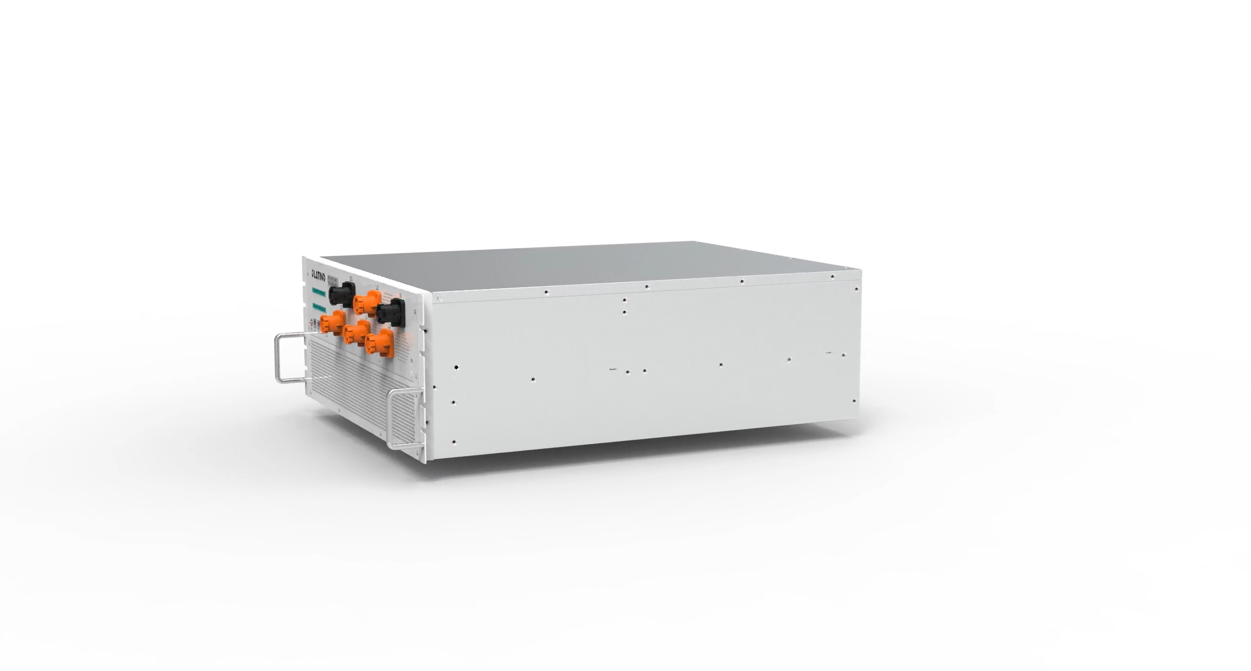
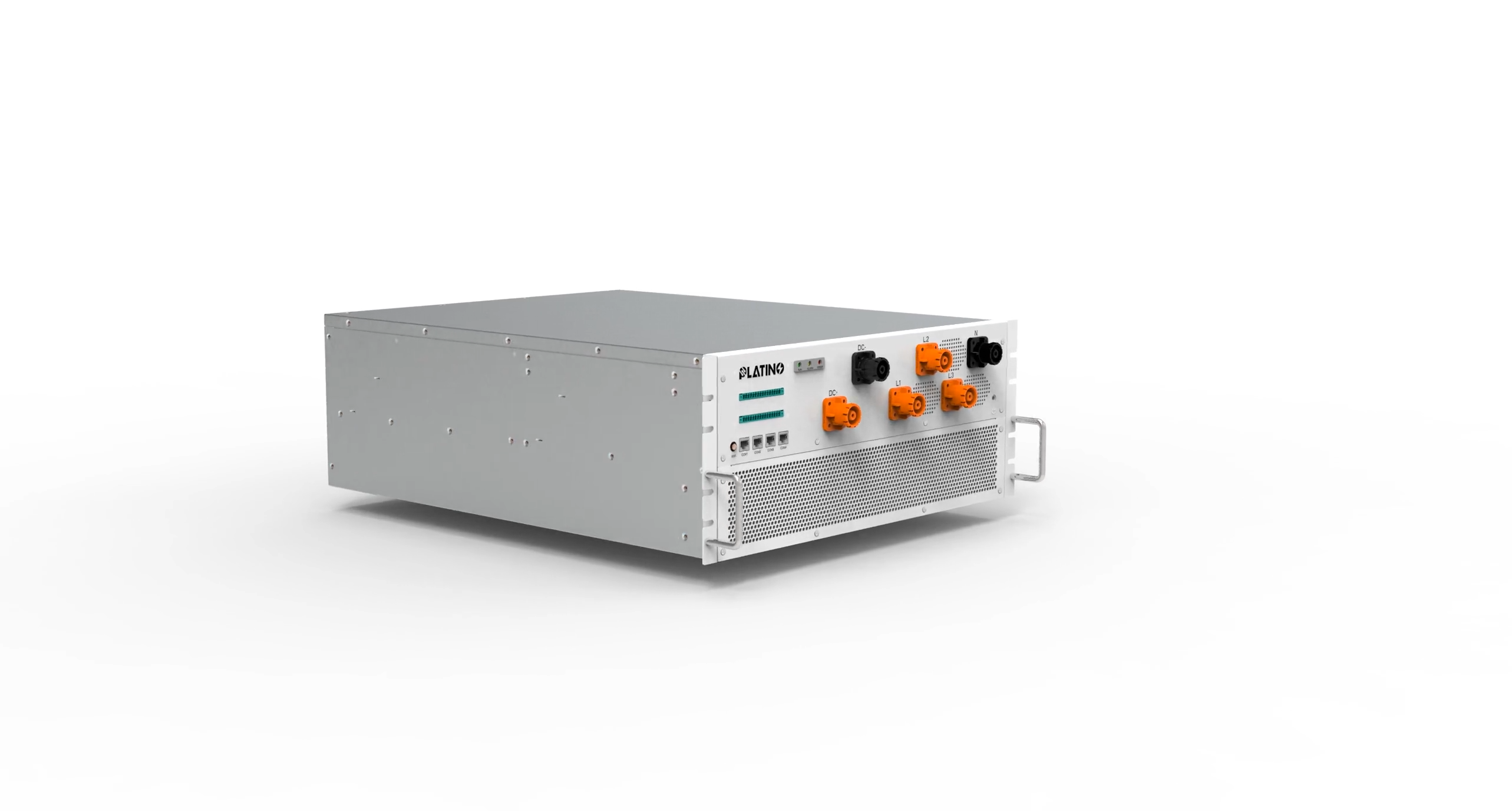
When a 130kW PCS enters peak discharge mode, the electrical and thermal stresses placed on its internal components reach their highest point. At this moment, every protective layer built into the system must function reliably and in coordination. A 130kW PCS that lacks well-designed safety architecture can fail suddenly, causing equipment damage, grid instability, or serious personnel hazards. Understanding how to ensure safety during peak discharge is therefore not a secondary concern — it is a core engineering and operational priority for anyone deploying a 130kW PCS in a real energy storage application.
A 130kW PCS is designed to convert stored DC energy from a battery bank into AC power delivered to the grid or local load. During peak discharge, this conversion process runs at or near rated capacity, meaning the 130kW PCS must handle maximum current flow, elevated switching frequencies, and sustained thermal output simultaneously. Without structured safety mechanisms, the risks multiply quickly. This article breaks down the key safety strategies that engineers and operators must apply to keep a 130kW PCS safe and stable throughout peak discharge cycles.
Electrical Protection Architecture of a 130kW PCS
Overcurrent and Short-Circuit Defense
The first line of safety for a 130kW PCS during peak discharge is a robust overcurrent and short-circuit protection system. When output demand spikes, a 130kW PCS must detect abnormal current levels within microseconds and respond with gate-drive shutdown or circuit isolation. A properly configured 130kW PCS uses IGBT modules with built-in desaturation detection, which senses collector-emitter voltage rise that indicates a fault condition. This allows the 130kW PCS to protect itself before a short-circuit event causes catastrophic semiconductor damage. The DC-side fuse and AC-side breaker ratings must also be matched precisely to the 130kW PCS operating range to avoid nuisance tripping or, worse, delayed interruption.
Overvoltage and Undervoltage Ride-Through
A 130kW PCS in peak discharge may encounter voltage swings on both the DC bus and the AC output. Overvoltage on the DC side, often caused by abrupt load shedding, can damage the power stage of a 130kW PCS if the system cannot clamp or absorb the transient energy. Active voltage clamping circuits and snubber networks are standard in a well-built 130kW PCS to handle such transients. On the AC side, a 130kW PCS must support grid voltage ride-through, meaning it stays connected and operational within a defined voltage band rather than tripping at the first deviation. This ride-through capability keeps the 130kW PCS contributing to grid stability even under disturbed conditions.
Thermal Management During 130kW PCS Peak Discharge
Cooling System Design and Redundancy
Thermal management is critical to 130kW PCS safety during sustained peak discharge. The power semiconductors inside a 130kW PCS generate significant heat when processing full rated current, and if junction temperatures exceed safe limits, IGBT failure or capacitor degradation can occur rapidly. A 130kW PCS designed for high-duty-cycle applications typically uses forced-air or liquid cooling, with redundant fan assemblies or pump modules to ensure cooling continuity. Thermal sensors embedded in the heatsink and near power modules give the 130kW PCS control system real-time temperature data. When the 130kW PCS detects thermal thresholds approaching, it can reduce output power, increase fan speed, or issue an operator alert before a fault escalates.
Derating Logic and Thermal Fault Handling
A well-engineered 130kW PCS incorporates automatic derating logic as a safety layer between normal operation and thermal shutdown. Rather than abruptly tripping offline, the 130kW PCS gradually reduces its output power as internal temperatures rise, maintaining partial service while preventing overtemperature damage. This soft-protection behavior extends the operational life of a 130kW PCS and reduces the frequency of hard faults. If temperatures continue to rise despite derating, the 130kW PCS will execute a controlled shutdown and log the fault event for diagnostic review. Operators of a 130kW PCS should regularly inspect cooling components and verify sensor calibration to ensure this thermal protection chain functions as intended.
Control Logic and Communication Safety in a 130kW PCS
Firmware Watchdog and Fault State Management
The digital control layer of a 130kW PCS plays a vital role in peak discharge safety. A 130kW PCS relies on its DSP or FPGA-based control board to execute modulation algorithms, manage protection thresholds, and maintain communication with the battery management system. If the control firmware enters an undefined state due to noise, memory error, or software hang, the 130kW PCS could operate with incorrect modulation or fail to respond to fault inputs. A hardware watchdog timer in a 130kW PCS continuously monitors the firmware execution cycle and forces a safe reset if the program stops responding. This ensures the 130kW PCS never remains in an uncontrolled active state during a control failure.
BMS Integration and Coordinated Discharge Control
A 130kW PCS must communicate continuously with the battery management system during peak discharge to enforce coordinated safety limits. The BMS sends real-time state-of-charge, cell voltage, and temperature data to the 130kW PCS so that discharge power can be adjusted before battery limits are violated. Without this communication link, a 130kW PCS could over-discharge the battery pack, triggering irreversible cell damage or a thermal runaway event. A 130kW PCS with reliable BMS integration will enter a hold or reduce-power state the moment BMS signals exceed defined thresholds. Testing this communication protocol under simulated fault conditions is an essential commissioning step before deploying a 130kW PCS in any peak discharge application.
FAQ
What protection features are most critical in a 130kW PCS during peak discharge?
The most critical features in a 130kW PCS during peak discharge are overcurrent protection, overvoltage clamping, thermal derating logic, and firmware watchdog timers. Each of these layers addresses a specific failure mode that becomes most likely when a 130kW PCS operates at full rated capacity. Together, they form a multi-layered safety architecture.
How often should the cooling system of a 130kW PCS be inspected?
For a 130kW PCS in active deployment, cooling system inspection should occur at least every three to six months. Dust accumulation, fan bearing wear, and coolant level changes can all reduce cooling efficiency in a 130kW PCS, making peak discharge operations more thermally risky. Regular maintenance ensures that the thermal protection chain remains reliable.
Can a 130kW PCS operate safely without BMS communication during peak discharge?
Operating a 130kW PCS without BMS communication during peak discharge is not recommended. A 130kW PCS without real-time battery data cannot enforce safe discharge limits, risking over-discharge, cell damage, or thermal events. Most professionally designed 130kW PCS units will halt discharge automatically if the BMS communication link is lost for more than a defined timeout period.