
 EN
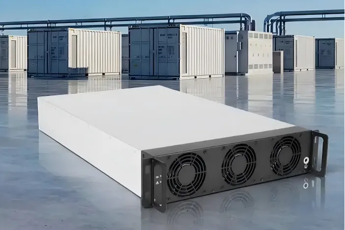
Bidirectional converters integrate renewable energy equipment by managing power that needs to move in both directions between sources, storage, loads, and the grid. In a solar-plus-storage system, for example, a converter can direct surplus energy into a battery, then return stored energy to a DC bus when generation falls. This makes bidirectional converters an important link between equipment that operates at different voltages and timescales.

Integration is not simply a matter of connecting terminals. Engineers must coordinate voltage ranges, current limits, control signals, protection, and the operating priorities of each device. The right design depends on where conversion occurs and which equipment sets the system voltage. Understanding these interfaces helps project teams evaluate bidirectional DC-DC converter applications and fit the converter into a complete renewable energy architecture.
Power interfaces between renewable equipment
Matching sources, storage, and DC buses
Renewable installations often combine a variable source, such as a photovoltaic array, with a battery whose voltage changes with its state of charge. A converter between the battery and a shared DC bus regulates that mismatch while allowing energy to flow toward or away from storage. This is one of the central bidirectional DC-DC converter applications in renewable systems, particularly when the battery cannot connect directly to the source bus.
Designers define the expected input and output voltage windows before choosing the interface. A converter must operate across the relevant battery range, handle the required direction changes, and respect current limits during charging and discharging. Reviewing bidirectional DC-DC converter applications at this stage helps clarify whether the unit will stabilize a bus, transfer energy between storage strings, or serve as a controllable link to another subsystem.
Coordinating conversion stages
A typical plant may use a DC-DC stage alongside a grid-facing inverter. The DC-DC stage manages the battery or another DC source, while the inverter converts DC power to AC and synchronizes with the utility connection. In these bidirectional DC-DC converter applications, the stages need compatible voltage limits, communication, and operating commands rather than isolated local settings.
System designers should map the complete energy path in both directions. During charging, the path may run from the grid or renewable source through an AC/DC interface and then into the battery. During discharge, stored energy can support an on-site load or pass through the inverter to the grid. Comparing these bidirectional DC-DC converter applications against the actual power paths exposes missing control responsibilities and prevents assumptions about which device regulates the bus.
Control coordination with the grid
Sharing duties with the inverter
Grid-connected equipment needs a clear division of control. The inverter typically handles synchronization, AC current commands, and grid response, while the DC-DC converter manages battery-side current and DC-link conditions. Effective grid-tied inverter control ensures these actions support one another: a request to export power must be matched by available DC energy, and a charging command must remain within source and storage limits.
Good grid-tied inverter control also defines how the system responds when renewable output changes quickly. The supervisory controller can request a power setpoint, while local controls enforce voltage, current, and temperature boundaries. Clear priorities matter when the battery is full, the grid limits export, or the source produces less than forecast. Grid-tied inverter control should not depend on a converter exceeding its safe operating envelope to satisfy a plant-level command.
Communication design is part of the control architecture, not an afterthought. Engineers specify how operating modes, alarms, measurements, and power commands pass between the converter, inverter, battery management system, and site controller. Well-defined grid-tied inverter control identifies which device owns each command and what happens if communications are delayed or lost. Local protections should remain active even when supervisory coordination is unavailable.
Managing grid events and operating modes
The operating sequence should cover startup, normal dispatch, shutdown, and fault recovery. For instance, the DC bus may need to reach an acceptable range before the inverter begins grid synchronization. Grid-tied inverter control can then ramp power according to site limits rather than apply an abrupt request. Testing this sequence helps confirm that the converter and inverter do not issue conflicting commands during transitions.
Project teams also need to account for utility requirements and the selected inverter’s capabilities. A system may be configured for self-consumption, demand management, backup support, or export, but each mode changes the role of storage and the acceptable direction of power flow. Consistent grid-tied inverter control ties those modes to real operating constraints, including battery state of charge, connection status, and permissible charge or discharge rates.
Deployment choices for storage and electric vehicles
Applying the interface to batteries and charging systems
In stationary storage, the converter can connect a battery whose voltage differs from the renewable plant’s DC bus. Engineers assess bidirectional DC-DC converter applications by checking power rating, voltage range, cooling, isolation needs, and how the system will be maintained. The electrical design should also define contactors, pre-charge arrangements, fusing, and measurement points so commissioning can verify safe operation in both directions.
Electric vehicle charging adds another controllable resource. With a compatible vehicle, charger, and site controller, energy may flow from the grid or renewable system into the vehicle and later return to a building or grid connection. Vehicle-to-grid power conversion describes this two-way transfer, but it depends on equipment and operating agreements that explicitly support reverse flow. A standard one-way charger cannot provide the same function simply through a software setting.
For a fleet depot, vehicle-to-grid power conversion can be planned around parking schedules, departure energy needs, site demand, and available renewable generation. The controller must avoid discharging vehicles below the energy reserve agreed for their next duty cycle. Vehicle-to-grid power conversion therefore needs coordination between charger limits, battery permissions, and the facility’s import or export boundary, rather than a power command based only on grid conditions.
A site integrating solar, stationary batteries, and EVs may combine several conversion stages. Vehicle-to-grid power conversion can complement stationary storage, but the site controller must allocate capacity according to connection status and priorities. Engineers should document whether vehicles charge first from solar, whether stationary storage is held for backup, and how export limits apply. These decisions make vehicle-to-grid power conversion a system-level operating choice, not merely a charger feature.
Commissioning for dependable operation
Commissioning should verify the complete sequence using realistic limits and failure conditions. Teams check measurements against calibrated instruments, confirm charge and discharge direction, test setpoint changes, and validate shutdown behavior. For bidirectional DC-DC converter applications, testing across representative voltage conditions can reveal whether control remains stable as the battery and DC bus change. The record should capture settings, alarms, and agreed operating boundaries.
Acceptance also needs to prove coordination with the inverter and site controller. Confirm that grid-tied inverter control observes export restrictions, that the DC stage responds to valid commands, and that protective limits override dispatch requests when necessary. Where vehicles are involved, validate permissions and reserve policies before enabling vehicle-to-grid power conversion. These checks connect the intended design with the behavior operators will rely on during everyday service.
FAQ
Can a bidirectional converter connect a battery directly to a renewable source?
It can provide a controlled interface between a battery and a DC source or bus when its voltage range, power rating, protections, and control functions suit the design. Bidirectional DC-DC converter applications vary, so confirm compatibility with the battery management system and the rest of the plant before specifying the connection.
Does the converter control the utility connection?
Not usually by itself. The inverter generally manages AC synchronization and grid-facing behavior, while the DC-DC stage regulates its DC-side transfer. Coordinated grid-tied inverter control assigns responsibilities and ensures that power commands respect equipment and utility limits.
What is required for vehicle-to-grid operation?
The vehicle, charging equipment, site controls, and connection must all support energy export. Vehicle-to-grid power conversion also requires operating rules for availability, battery reserves, and permitted power. Confirming those conditions distinguishes a genuinely bidirectional system from ordinary one-way charging.